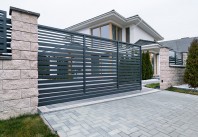
Porti rezidentiale DECORIO
p. 41, 50, 56 and 68.
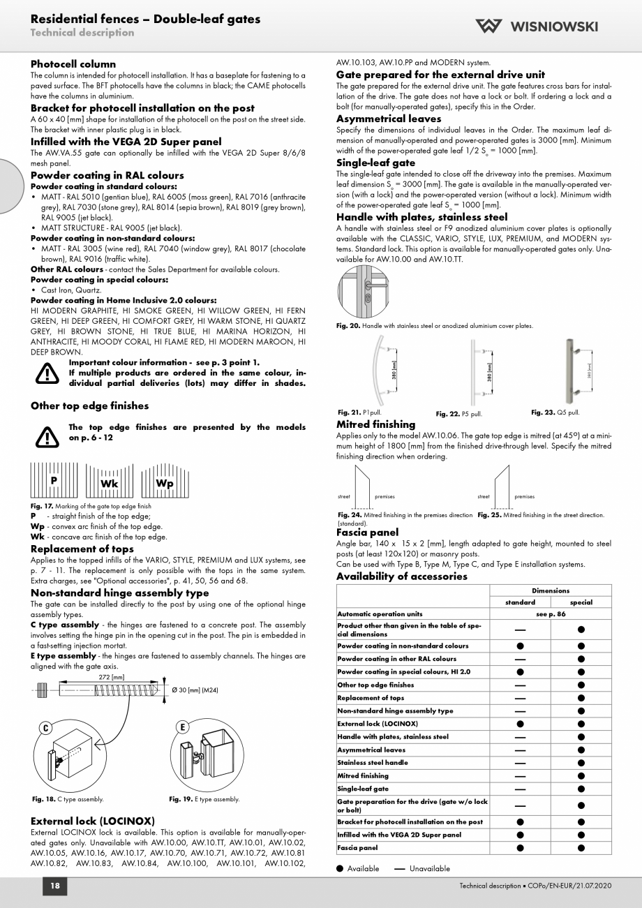
- optional accessory for extra charge). The 120 x 80 [mm] carrying shape
(the wheels are integrated in the shape). Due to the variances in the clearance
it is recommended to choose the ordering height with the following formula:
H = Hr - 30 [m m].
Other top edge finishes
The top edge finishes are presented by the models on p.
6 - 12.
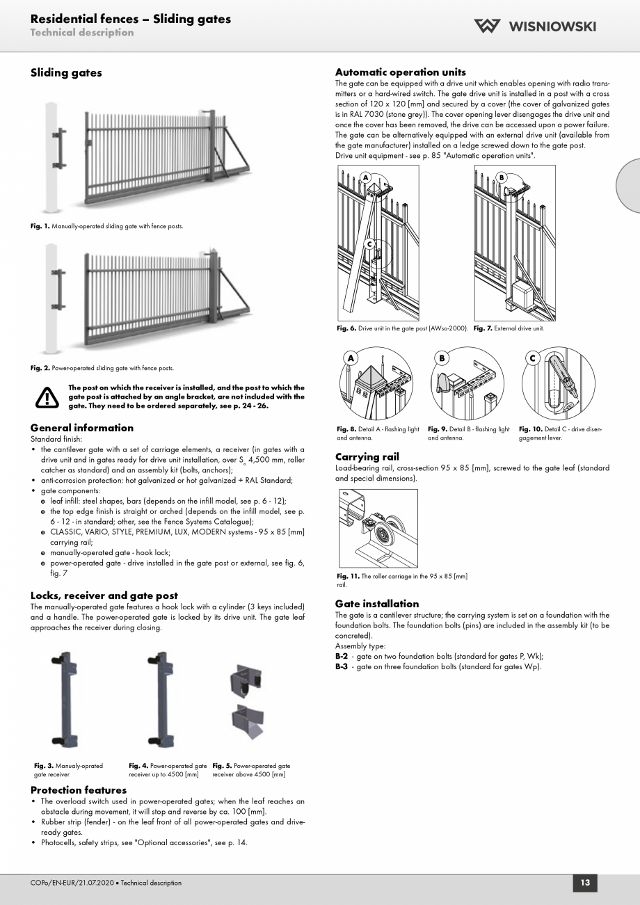
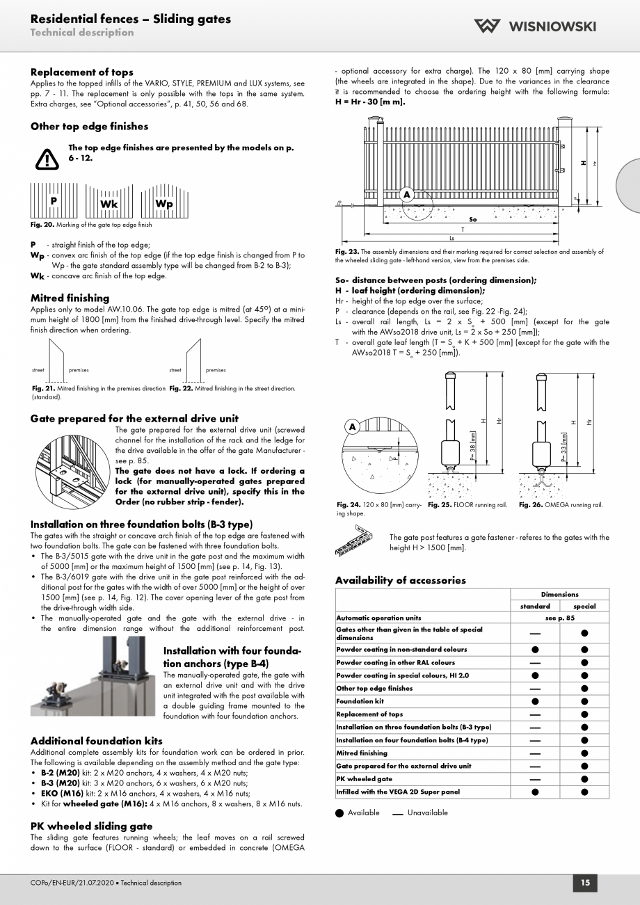
Fig. 20. Marking of the gate top edge finish
P - straight finish of the top edge;
Wp - convex arc finish of the top edge (if the top edge finish is changed from P to
Wp - the gate standard assembly type will be changed from B-2 to B-3);
Wk - concave arc finish of the top edge.
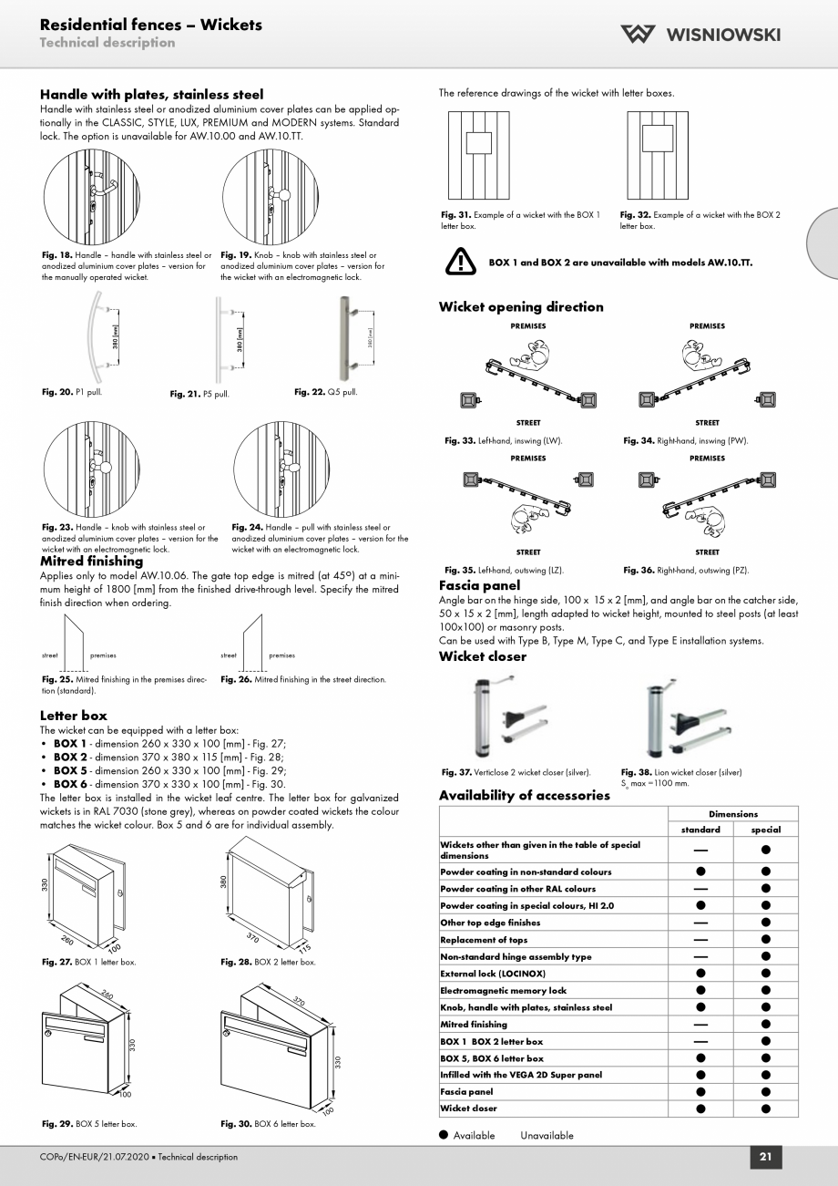
Mitred finishing
Applies only to model AW.10.06. The gate top edge is mitred (at 45o) at a minimum height of 1800 [mm] from the finished drive-through level. Specify the mitred
finish direction when ordering.
street
premises
street
Fig. 23. The assembly dimensions and their marking required for correct selection and assembly of
the wheeled sliding
... ascunde