Instalarea panourilor din fibrociment pentru fatade ventilate CEMBRIT Cover, Solid, Transparent
Tip documentatie: Instructiuni montaj, utilizare
Salvează pdf
Full screen
ambient temperature should be +5 °C - +30
°C and relative humidity <85 % . Process temperature must be
min +5 °C.
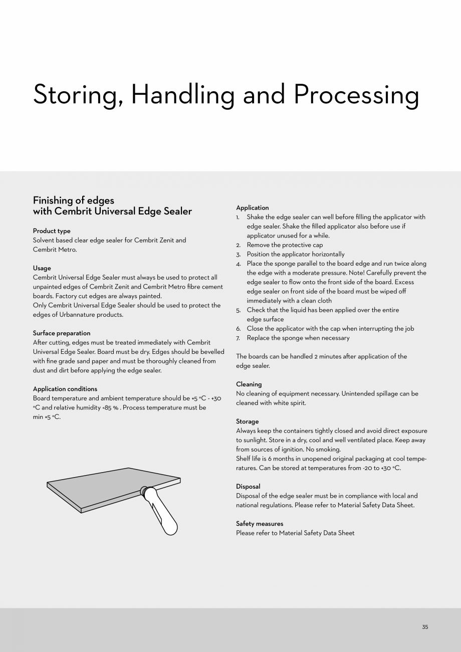
Application
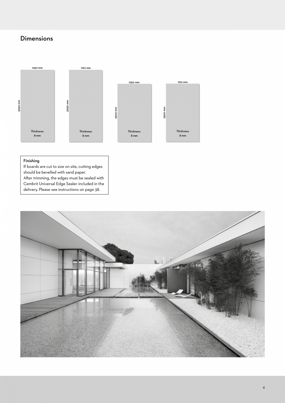
1. Shake the edge sealer can well before filling the applicator with
edge sealer. Shake the filled applicator also before use if
applicator unused for a while.
2. Remove the protective cap
3. Position the applicator horizontally
4. Place the sponge parallel to the board edge and run twice along
the edge with a moderate pressure. Note! Carefully prevent the
edge sealer to flow onto the front side of the board. Excess
edge sealer on front side of the board must be wiped off
immediately with a clean cloth
5. Check that the liquid has been applied over the entire
edge surface
6. Close the applicator with the cap when interrupting the job
7. Replace the sponge when necessary
The boards can be handled 2 minutes after application of the
edge sealer.
Cleaning
No cleaning of equipment necessary. Unintended spillage can be
cleaned with wh
... ascunde
Alte documentatii ale aceleasi game Vezi toate
Catalog, brosura
1 p | EN
Cover Patina Solid Transparent
Fisa tehnica
3 p | EN
Patina